Tryston here! Today I’m going to explain what a serger is and help take the fear out of sewing with one! I’ll also be answering some common questions!
What is a Serger?
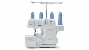
A serger is a sewing machine that binds fabric together with an overlock stitch. It uses 3-4 stitches to create the overlock stitch. This is the finishing stitch you see on many of your shirts and garments that you have around the house right now.
What does a serger do?
A serger trims the seam and encloses the seam allowance or edge of the fabric, inside a thread casing, all in one step. The width and density of the stitching are two of the many variables available on a serger. The options are not the same on all sergers. As with almost anything you purchase, the more you spend, the more options you will have. But mostly all basic sergers around the 200-300 range work perfectly for home use.
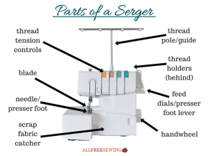
Part of a serger
The dials you see on top of the machine are the tension settings for your thread. From left to right, they are:
left needle
right needle
upper looper
lower looper
**Please note that most sergers do look the same so even if you have a different type than this the chances are they will still be very similar to this.
Left of the machine.
Adjust the stitch width and length
Turn the knife on or off
The stitch width and length/ There are times when you may want to turn your knife off.
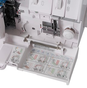
Inside:
The main thing that sets sergers apart from sewing machines is the loopers. These are located inside the machine and under the needle.
The loopers act like knitting needles, in that they overcast over the needle threads.
The loopers are threaded in a special sequence.
Many machines include a threading chart right on the machine, for an easy reminder when threading the serger.
Written By: T. Bruner
-Stay tune to the next post: How to thread a serger-
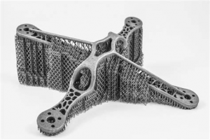
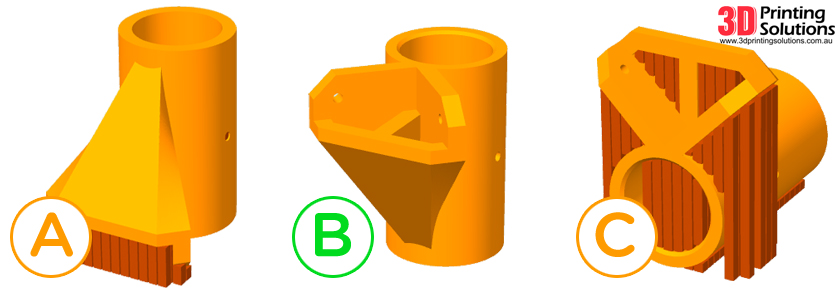
Supports are extra plastic material printed on or around the object you are printing to help make it print and look better.
Example:
When do you need supports?
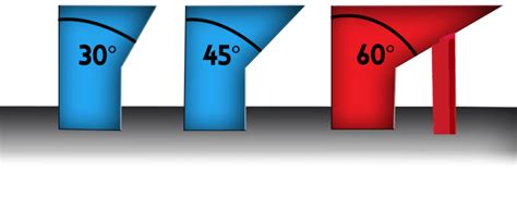
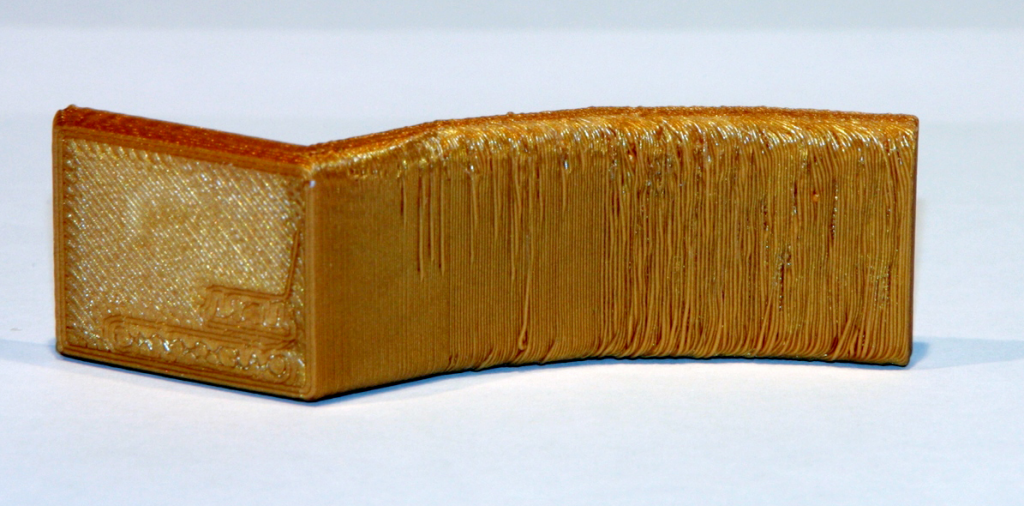
It is best to use supports when printing an object that has overhangs greater than 45 degrees. Overhangs are a diagonal part of the print where some of the top layer is printed on top of the bottom, and the rest goes past the previous layer with nothing underneath. The steeper the overhang means more material will be printed with nothing under it, causing it to droop, and create a poor surface of the part. Supports give the part something to for the object to print on when it moves past the previous layer. This holds up the parts to reduce the drooping effect as much as possible and allow the object to retain its intended shape.
Overhang example:
Drooping effect:
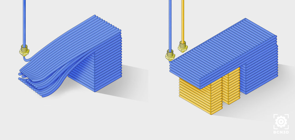
Object with overhang (without and with support):
How to reduce supports?
Supports are useful, but they increase the time it takes to print an object and increases the amount of material you must consume per part. Reducing supports can help save you time, material, and money. Here are some ways to reduce supports for your parts:
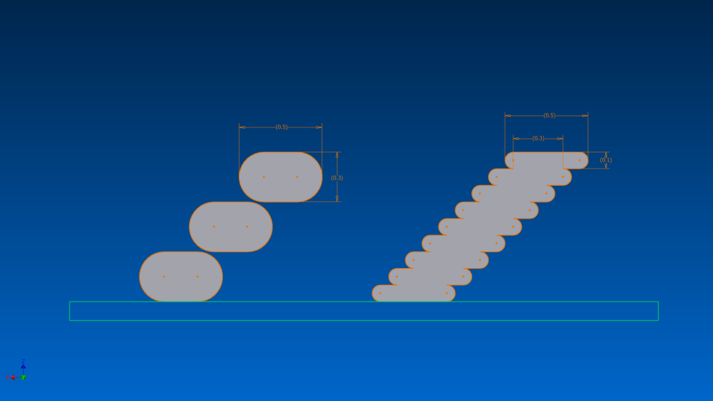
One option is to reduce the layer height you are printing the object with. Layer height is the vertical thickness of each individual layer of the print. When you have a smaller layer height, the layer does not have to extend as far out with each layer when there is an overhang. This makes printing the overhang easier for the printer without support because more of the layer will be printed on the layer before it, improving quality. The downside to this is printing with smaller layer heights takes much longer for the object to print because the nozzle is having to complete many more travel moves.
(Each level represents a single layer on both sides. You can see how far off out each layer must travel on the left. When the layer height is reduced on the right, a much smaller outward distance is traveled by each layer.)
Another option is to alter the object itself to include as little overhangs as possible that exceed 45 degrees. If you were the one who designed the part, that makes it very easy to go in and edit the original file. If the file is an object you found online, that makes it slightly more difficult to make the alterations you need. Having overhangs over 45 degrees is not a deal breaker, all it means is you will need to do a little more work getting the part to come out how you want it.
One more option is to experiment with the object’s orientation. Orientation is the position in which the object will rest on the print bed. By changing the objects orientation, you are also changing the overhang angles without altering the shape of the object. With certain objects, you may be able to remove all overhangs simply by changing the orientation.
Ex.
the vertical pillars represent support material. For A. there is very little support, but still some at the base. By rotating the object 180 degrees B. can print with no support at all, and no change to the objects shape. C. can still print, but it was rotated in such a way that even more support material is added than necessary, so be careful that you are printing in the best orientation possible.)
What are some problems with supports?
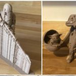
The biggest issue with supports comes with post-processing. Post-processing is the extra work you need to do to the object after it is done printing to make it look like it is supposed to. When printing with support, you need to manually remove it from the print, it does not simply go away when done. If your support settings are not well set, the support can almost seem glued to the object, and you can spend large amounts of time chipping that support material away until it is all off. If your settings are better set, then once you remove the object from your build plate you may be able to hold the object in one hand and pull the support material off in other with one motion. Dialing in you print settings takes time, along with trial and error, but once you can make it work for you it can save you a lot of time overall.
Ex.
Another issue is surface quality. Yes, support helps with drooping to improve surface quality, but it is also sticking to your object. Once that material is removed from the object, wherever the support was touching will leave a scar on the object from being pulled off. A way around this is to finish the surface with sandpaper/other abrasives or paint the object to smooth it out.
Lastly, one problem with supports is environmental. The support material, after being taken off the object, becomes waste and is thrown away. That is extra plastic that you are using that serves no function and goes straight into the trash after printing. That being said, the most common 3D printing filament is PLA, which is a starch-based plastic derived from plants, meaning it is biodegradable. This is not the case for most others however, so keep that in mind when printing with other types of materials.
One more Solution:
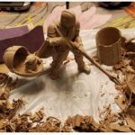
Some printers have more than one nozzle, meaning they can print more than one material at a time. There is water-soluble filament (meaning the filament can dissolve in water) that can be used as support material. You can print the object you want with one nozzle and material, while the water-soluble support material is printing through the other nozzle. Once the print is finished, you can take the entire print off the bed, place it in water, and the support material will dissolve away. This greatly reduces the hassle of post-processing and leaves a much better surface finish by eliminating the concern of scaring the surface when pulling the support material off the part. If this is a viable option for anyone with access to a dual head printer, I recommend this as the best way to print complex object and maintain the highest level of surface quality.
Ex.
(Right image is the object after support material is dissolved. Left image shows to water-soluble filament still attached to the object)
To finalize and remove any discrepancies in our code, it is best to get rid of any unnecessary code. For example, to test the solving function, I had a test board with fixed values. One important rule is to never hardcode or fix values. This is fine for testing; however, we want the user to have full control to ensure future usability.
We also want to shorten and optimize our code. From the beginning, I emphasized that functions were the best way to code. It is much faster to debug specific areas in our code. We can also simplify things by utilizing object-oriented programming. We can have a functions file and the main driver on another main file. This will make our code easier to test, read, and optimize. Since we have a better understanding of our code and the project, many functions can be simplified. It is good practice to take breaks and step away during this step. It is easy to later question why you made some functions more complicated than they should be.
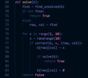
Now that our code is clean and debugged, we can add a Graphical User Interface. We are using a library called PyGame, widely used in Python for small games and early game development. A library adds lots of predefined functions that we can utilize. First, we will draw our board using simple statements in PyGame. Since we have already determined what the user can do, we have a roadmap. We will use the same functions, but modify them for our board. We must create a sketch, draw, select, place, clear, and an update function. We can also create a nice GUI update to show our backtracking algorithm. PyGame has useful draw and event functions for keyboard presses and formatting. The two screenshots are of my previous code and the updated GUI code with PyGame.
The left screenshot is my outcome. I allowed the user to play and have the solving algorithm run if they choose. I created an executable and setup wizard as well so others can download and install the game using a simple plugin installed similar to PyGame called Cx_Freeze. With this, I can change the logo of the executable, create a setup wizard, and so much more. I hope you enjoyed coding this project with me and implemented new functionalities to your liking.
To begin, we will write our code in an ideal editor. I am going to use Visual Studio Code because it has a nice design and useful extensions to help increase the workflow. However, something as simple as Notepad is enough.
We will need multiple functions to keep things clean. When coding, it is a good practice to indent your loops and functions cleanly and intuitively as it is easier to read. It is also important to use unique but informative comments and variable names. Naming a variable or a function, “A, A1, B, B1, B2,” is never helpful to you or anyone reading your code. This will ensure quicker debugging instead of staring at your screen for hours because you forgot about a semicolon.
Now that we have an environment, we can work on coding. Since we have a basic idea of Sudoku and what functions a user can do, we will first make the board. The board is a simple matrix, and we will initialize all the values to zero. We will make a print function for it as well for easy debugging.
To create a new unique solvable board, we must work backward. Sudoku is solved when all numbers counting 1-9 are entered and the constraints are passed. As we know, the constraint is that two numbers cannot be in the same row, column, or 3×3 grid. We can do this by implementing the backtracking algorithm. We will be able to make sure a given board can be solved and increase/decrease difficulty per the amount of numbers shown.
The backtracking algorithm is simple. Look for an unanswered spot on the board, pick a number, and continue forward. If there is a conflict, go back to where the problem occurs, and pick a different number. Then keep repeating the process until the board is completely solved. We must make sure to do this algorithm with time complexity in mind. If we do not check for the constraints first and instead test every number from 1-9, it will take a long time as this is very inefficient. This can be similar to the brute force algorithm. Every box has a possibility between 1 through 9. Therefore, we would have to test a maximum of 9^81 values as simple probability suggests.
Once we have made a function for solving the board and checking for an unsolved spot, we can continue. The algorithm will create new unique boards by itself. We will have to keep the solved solution so we can test the user on it later. Some numbers can be revealed by picking a random spot in the empty table and copying that same spot on the solution to show up onto the unsolved board. We can do this as many or as little times as we want. Now that we have the unique unsolved user board and the solved solution, we can start on the GUI or the Graphical User Interface.
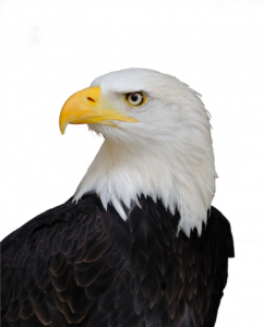
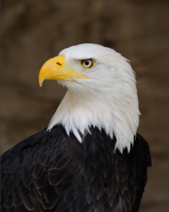
For this tutorial we will be making a 3D representation of this image:
Credit: Saffron Blaze, Wikimedia Commons
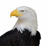
Being able to take a picture of an item and turn it into a 3D model can be a very useful skill. This is a multi-step process that begins with the picture, then utilizes photo editing programs, vector manipulation, and finally Tinkercad. First you need to take your picture and open it some kind of photo manipulation program… I prefer to use Photoshop because it has good selection tools. In the program you should work to cut out the background from the image (see P1). In this case, I simply used the magic wand selection tool in Photoshop and deleted the background.
P1:
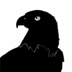
Next, you will want to selectively remove an outline of any details you want to keep in your image… in this case, we’ll keep the eye, nostril and outline of the neck. (see P2). Then select all of the white areas of the image and use the inverse selection option to select the opposite area of the image instead. Now with this area selected, color the whole selection one color (see P3). After this… just clean up any of the rough edges and save the file as a .BMP file.
P2
P3
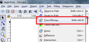
The next step is to change our .BPM image into a vector image, specifically a .SVG image. To do this I use the free program Inkscape, but you could also use Adobe Illustrator. Once you open the file in Inkscape, it will bring up a pop up window with some options to pick from. You should choose “Default import resolution” for DPI and “Smooth” for Image Rendering Mode. Click on your Image and go to Path à Trace Bitmap (see P4) and click it. A window will open up. Click the Update button and then Okay and you can close the window. Now delete the .BMP image (identifiable by the way it gets blurrier as you zoom in on it.) and save the file as an .SVG.
P4:
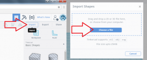
For this next step, we will use yet another free program… this time called Tinkercad. First you need to make an account, or sign in via Facebook, and then open up a new project. Now go and click the import button and upload the .SVG file to the program (see P5). Sometimes the file will be too large to import… if this is the case the just use the scale feature to reduce the scale until it will fit into Tinkercad’s plane.
P5:
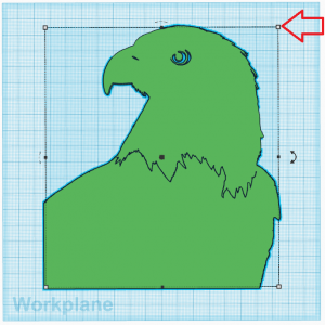
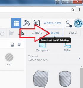
Next you can scale the object to the size you want with white and black squares located in near proximity to the model (see P6). Holding shift while moving the white squares will uniformly scale the model to as to avoid warping the features. Once you have to model the size you want, you can export it (see P7) as an .STL (for 3D printing) or .OBJ (for more general purpose modeling) and save it to your computer. And you’re done!
P6:
P7:


 We also want to shorten and optimize our code. From the beginning, I emphasized that functions were the best way to code. It is much faster to debug specific areas in our code. We can also simplify things by utilizing object-oriented programming. We can have a functions file and the main driver on another main file. This will make our code easier to test, read, and optimize. Since we have a better understanding of our code and the project, many functions can be simplified. It is good practice to take breaks and step away during this step. It is easy to later question why you made some functions more complicated than they should be.
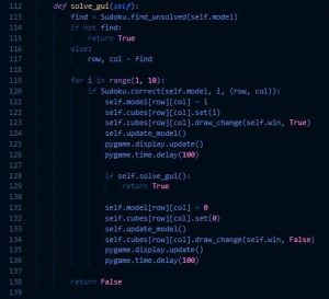 Now that our code is clean and debugged, we can add a Graphical User Interface. We are using a library called PyGame, widely used in Python for small games and early game development. A library adds lots of predefined functions that we can utilize. First, we will draw our board using simple statements in PyGame. Since we have already determined what the user can do, we have a roadmap. We will use the same functions, but modify them for our board. We must create a sketch, draw, select, place, clear, and an update function. We can also create a nice GUI update to show our backtracking algorithm. PyGame has useful draw and event functions for keyboard presses and formatting. The two screenshots are of my previous code and the updated GUI code with PyGame.
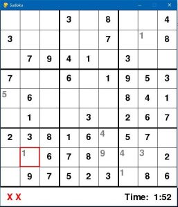 The left screenshot is my outcome. I allowed the user to play and have the solving algorithm run if they choose. I created an executable and setup wizard as well so others can download and install the game using a simple plugin installed similar to PyGame called Cx_Freeze. With this, I can change the logo of the executable, create a setup wizard, and so much more. I hope you enjoyed coding this project with me and implemented new functionalities to your liking.
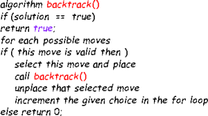

 Credit: Saffron Blaze, Wikimedia Commons